Author: Daniel Brown

  • Ambisonics Monitoring in Davinici Studio

    Ambisonics Monitoring in Davinici Studio

    Ambisonics Monitoring and Spatial Routing in Davinci Resolve Studio 21

    Step-by-Step Guide: Ambisonics Monitoring & Spatial Routing in DaVinci Resolve Studio 21

    To successfully manage Ambisonics first-order (1st order, 4-channel) project while  monitoring ambisonics safely in standard stereo on a Windows machine, you need a precise routing matrix inside DaVinci Resolve Studio 21.

    Because Windows sound drivers and standard headphones cannot decode raw 4-channel spatial fields natively, we will set up Bus 1 as your master 4-channel Ambisonic deliverable, and Bus 2 as a dedicated stereo downmix/monitoring line equipped with an Ambisonic-to-Stereo decoder plugin.

    Here is the comprehensive, step-by-step setup guide from timeline creation to final export.


    Step 1: Timeline Creation & Ambisonics Audio Configuration

    Before dropping any files onto your timeline, the master sequence must be explicitly configured to accept multi-channel spatial data.

    1. Open DaVinci Resolve Studio 21 and go to the Project Settings (the gear icon in the bottom-right corner).
    2. Under Fairlight, ensure your Timeline Audio Spatial Audio Format is supported (leave on default or off, as we will define the bus properties manually). Click Save.
    3. Go to the Edit Page. In your Media Pool, right-click and select Timelines > Create New Timeline…
    4. In the dialog box, uncheck “Use Project Settings” and click on the Audio tab.
    5. Change the Main Track Type dropdown from Stereo to Adaptive 4.

    Why Adaptive 4? Ambisonics 1st order requires exactly 4 discrete audio channels wrapped together into a single track mapping (W, X, Y, Z). An Adaptive 4 track layout allows Resolve to process these 4 channels bound together cleanly without splitting them into separate mono strips.

    1. Click Create.

    Step 2: Setting Clip Attributes for Ambisonics Assets

    If your raw 360 audio file or spatial microphone WAV files are imported, Resolve might misinterpret them as 4 separate mono tracks or a standard quadraphonic layout. You must force the clip properties to recognize the Ambisonic architecture.

    1. In the Media Pool, right-click on your raw spatial audio clip and select Clip Attributes…
    2. Navigate to the Audio tab inside the Clip Attributes window.
    3. Change the Format dropdown from Mono or Stereo to Ambisonic Regular (or Adaptive 4 depending on your exact spatial mic file type; Ambisonic Regular automatically flags the metadata for standard W, X, Y, Z FuMa or AmbiX layout).
    4. Ensure the track allocation matches Tracks: 1 and channel assignments map linearly (Channel 1 to Embedded Ch 1, Channel 2 to Embedded Ch 2, etc.). Click OK.
    5. Drag this clip onto your new timeline. It will populate into your Adaptive 4 track (labeled A1).

    Because you want to combine both the 360 soundscape and your background stereo elements for YouTube, we will use YouTube’s official hybrid delivery standard: First-Order Ambisonics with Head-Locked Stereo (a 6-channel payload). Channels 1–4 are explicitly reserved for your moving spatial field (W, X, Y, Z), and Channels 5 and 6 carry your flat, head-locked Left and Right stereo music.


    Step 3: Setting Up Bus Formats & Assignments for Ambisonics

    1. Configure the Bus Formats

    Go to Fairlight > Bus Format. Keep your exact layout names, but adjust the structural channel width dropdowns to match this layout:

    Bus Bus Name Format (Dropdown Menu) Purpose
    B1 AmbisonicsSubmix Adaptive 4 Pristine, un-decoded pass-through for just your spatial mic tracks.
    B2 StereoMonitor Stereo Your Main Mixing Line & 3DVista Master. Everything flattens cleanly here.
    B3 YouTubeMaster Adaptive 6 Your Final YouTube Master. (4 Channels Ambisonic + 2 Channels Stereo).
    B4 AmbisonicsMonitor Adaptive 4 Dedicated Plugin Slot. Holds dearVR (AmbiX to Binaural).

    2. The Exact Bus Assignment Matrix for Ambisonics

    Go to Fairlight > Bus Assignment. We will map your 7 individual tracks and link your sub-mixes using clear logic gates.

    A. The Stereo Elements (Tracks 1, 2, 3 – Music & Stereo Loops)

    Route them to B2 and B3 only:

    • Tracks 1, 2, 3 -> Bus 2 (StereoMonitor)
    • Tracks 1, 2, 3 -> Bus 3 (YouTubeMaster)
    • Crucial Setting for Bus 3: Because YouTubeMaster is an Adaptive 6 bus, look at the channel mapping/output settings for Tracks 1, 2, and 3 going to Bus 3. Ensure they are explicitly routed to target Channels 5 and 6. This perfectly separates your background music into the designated “head-locked stereo” channels for YouTube!

    B. The Spatial Elements (Linked Tracks 4–7)

    Route your linked spatial environment microphone tracks to B1, B2, and B4:

    • Linked Tracks -> Bus 1 (AmbisonicsSubmix)
    • Linked Tracks -> Bus 2 (StereoMonitor) (Fairlight automatically flattens it flat to standard stereo here alongside your music!)
    • Linked Tracks -> Bus 4 (AmbisonicsMonitor)

    C. Injecting the Sub-Buses (Bus-to-Bus Routing)

    Look at the bottom left of the matrix grid under the Buses category:

    • Bus 1 -> Bus 3 (YouTubeMaster): Ensure Bus 1 maps directly to Channels 1, 2, 3, and 4 of Bus 3. This puts your clean 360 audio exactly where it belongs.
    • Bus 4 -> Bus 2 (StereoMonitor): Pipes the 3D binaural decoded headphone mix from the plugin right to your master monitoring line.

    3. Visual Routing & Signal Flow

    This layout visualizes how the different formats travel through your sub-mixes to populate the hybrid 6-channel final render block:

    Source Audio Streams Primary Sub-Buses (Processing) Final Target Destinations
    Stereo Tracks 1-3
    (Background Music / Sound Effects)
    Bypasses Spatial sub-mixes completely to avoid processing interference

    ➔ Bus 3: YouTubeMaster
    (Hard-routed to Channels 5 & 6 only)

    ➔ Bus 2: StereoMonitor
    (Standard L/R mixout)

    Spatial Tracks 4-7
    (Linked 4-channel microphone arrays)

    ➔ Bus 1: AmbisonicsSubmix
    (Main 360 Volume Matrix)

    ➔ Bus 4: AmbisonicsMonitor
    (Plugin engine: Decodes AmbiX to Binaural 3D)

    ➔ Bus 3: YouTubeMaster
    (Bus 1 feeds linear channels 1, 2, 3, & 4)

    ➔ Bus 2: StereoMonitor
    (Bus 4 feeds head-tracked 3D audio loop)


    Step 4: Set Your Plugin & Control Room Monitoring for Ambisonics in Stereo

    Phase 1: Downloading & Installing the Software

    Because the native Sennheiser website newsletter reCAPTCHA is famously buggy, you must download the unified installer package from the preserved community links (like the verified Reddit resource threads here: https://mautic.sennheiser.com/r/0dcede9a491c36d51ca7200e0. Just a warning: This is the whole DearVR Suite and the download is over 3 GB).

    1. Download the Package: Locate and download the offline installer folder containing dearVR AMBI MICRO v1.10.0 and the dearVR Spatial Connect suite. You do not need the other apps to monitor your ambisonics.
    2. Run the Installer: Open the .exe file on your Windows machine.
    3. Select Formats: When prompted, ensure VST3 is explicitly checked. This is the format DaVinci Resolve Studio 21 requires to read multi-channel audio tracks properly.
    4. Choose Components: Ensure you check the boxes for:
      • dearVR AMBI MICRO VST3
      • dearVR Spatial Connect (Main App)
      • dearVR Spatial Connect Adapter
    5. Restart Your PC: Once installation finishes, restart Windows to cleanly initialize the new audio drivers and network ports.

    Phase 2: Configuring the Windows & VR Connection Loop

    To get head-tracking working without a final 360° video, we use Dear Reality’s built-in virtual studio environment to host the tracking data loop.

    1. Initialize Link: Plug your Meta Quest into your PC via your Link Cable. Put the headset on, enable Quest Link, and ensure you can see your virtual Windows desktop screen inside the headset.
    2. Launch the Main App: On your Windows desktop, open the standalone application named dearVR Spatial Connect.
    3. Configure a Virtual Room:
      • Click on the Settings gear icon inside the app.
      • Go to the BACKGROUND dropdown menu. Since you don’t have a 360° video yet, select a virtual layout like Multichannel Studio, Cinema, or *Main Space Grid*.
    4. Set the Data Ports:
      • In the same settings panel, turn the DEARVR HEADTRACKING toggle switch to ON.
      • Locate the VST OSC PORT OUT box and type in the standard tracking port: 7001.
    5. Launch & Link the Adapter:
      • Go to your Windows desktop taskbar (bottom right corner), click the ^ arrow to show hidden icons, and look for the Spatial Connect Adapter tray icon.
      • Right-click the icon and select Settings.
      • Change the Protocol dropdown menu to **Spatial Connect**.
      • Set the Head Rotation Port to match exactly: 7001.
      • Click Apply.
      • The status logo on the adapter window will instantly flip to Connected.

    Phase 3: Routing the Audio Buses in DaVinci Resolve

    Now we must build a clean, bulletproof routing path inside the Fairlight page that isolates your raw spatial audio mathematics from your standard headphone outputs.

    1. Open the Project: Launch DaVinci Resolve Studio 21 and head straight to the Fairlight Page.
    2. Configure Studio Preferences:
      • Go to DaVinci Resolve > Preferences > System > Video and Audio I/O.
      • Set your main Audio Output Device to Headphones (Oculus Virtual Audio Device) or Oculus Link Audio.
      • Set the Monitor Speaker Configuration format to Stereo (2.0), ensuring Channel 1 maps to Left and Channel 2 maps to Right. Click Save.
    3. Create the Bus Layout: Open the Fairlight top menu bar, select Bus Format, and build four dedicated paths:
      • Bus 1 (AmbisonicsSubmix): Set Format to Adaptive 4. (This is your master spatial mixing engine).
      • Bus 2 (3DVistaDownmix): Set Format to Stereo. (For flat 2D web-tours, if needed later).
      • Bus 3 (YouTubeExport): Set Format to Adaptive 6. (This is your final 6-channel render bus).
      • Bus 4 (AmbisonicsMonitor): Set Format to Stereo. (This sends the final 3D audio to your headset).
    4. Map the Bus Connections: Go to Fairlight > Bus Assignment and establish these exact, clean link nodes:
      • Route your Spatial Audio Timeline Tracks directly into Bus 1.
      • Route Bus 1 out into Bus 4 (to send the raw sphere to the monitoring decoder).
      • Route Bus 1 out into Bus 3 (to feed the spatial data to your YouTube exporter).

    Phase 4: Setting Up the Plugins to Monitor the Sound

    With the routing built and the data ports wide open, we load the plugins and decode the math into a real-time, head-tracked 3D headphone mix.

    1. Load the Monitoring Decoder:
      • Go to your Fairlight mixer panel and look at the vertical strip for Bus 4 (AmbisonicsMonitor).
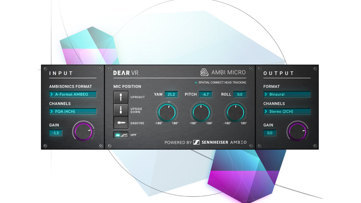
      • Click the + icon in its Effects slot and insert dearVR AMBI MICRO v1.10.0.
    2. Configure the Plugin Math: Open the plugin window and set the parameters:
      • INPUT FORMAT: Set to AmbiX (this decodes the 4-channel W, X, Y, Z spatial data pipeline correctly).
      • OUTPUT FORMAT: Set to Binaural (Headphones).
    3. Verify the Tracking Light: Look at the tracking connection indicator inside the plugin interface. Because the background adapter app is actively feeding data from your Quest, the light will instantly turn a solid GREEN.
    4. Perform the Physical Check: Put your Meta Quest headset on and hit the spacebar to play your audio timeline. Physically turn your head 90 degrees to the left. The audio landscape will instantly anchor itself to the virtual room, forcing sounds that were directly in front of you to hit your right ear dynamically.
    5. How to Mix and Adjust Content:
      • Go to the vertical mixer strip for Bus 1 (AmbisonicsSubmix) and drop an identical instance of dearVR AMBI MICRO v1.10.0 into its effects rack.
      • Look at your video timeline viewer. If a sound source is visually located 45 degrees to your right, open your Bus 1 plugin and use your mouse to twist the Yaw knob until the internal sound visualizer ball matches the 45-degree angle.
      • Because your Bus 4 pipeline is successfully decoding head-movements via your Quest, you can turn your head freely and hear your adjustments lock perfectly into 3D space with absolute technical precision before you ever click export.

    Step 5: Exporting Your Separate Deliverables

    When you enter the Deliver Page, your bus configuration keeps your two outputs perfectly partitioned:

    Exporting for 3DVista (The Balanced Flat Master)

    1. In the Render Settings Audio tab, set Output Track 1 to Bus 2 (StereoMonitor).
    2. Set Channels to 2.
    3. Result: Your background music and your naturally flattened 360 environment are combined into a clean, flat Left/Right web-friendly stereo mix.

    Exporting for YouTube VR (The Professional 6-Channel Hybrid)

    1. Change Output Track 1 to Bus 3 (YouTubeMaster).
    2. Set Channels to 6.
    3. Result: A pristine 6-channel master file. Channels 1–4 contain your raw, un-compromised 1st order Ambisonic spatial environment, completely untouched by the monitoring plugin. Channels 5–6 carry your clean stereo background music.
    4. Run this file through your FFmpeg tool and check both boxes (“Spherical” and “Spatial Audio”) inside the Metadata Injector app. YouTube will process it flawlessly!

    About the Author:
    Daniel John Brown is a VR photographer, videographer, and founder of Meidansha. Based in Japan, he specializes in high-resolution immersive media and technical post-production workflows.

    • Business & Portfolio: Connect with my corporate team at Meidansha.

    To see more on 360 photography and videography please see the category top


    DaVinci Resolve Studio 21 で構築するアンビソニックス監視ワークフロー

    フィーチャー画像はゼンハイザー提供

    標準のWindowsマシンにおいて、第1次アンビソニックス(1st order、4チャンネル)プロジェクトを安全にヘッドフォンでステレオ監視(モニタリング)しながら、完璧に編集・ミキシングするには、DaVinci Resolve Studio 21内部で厳密なオーディルートをマッピングする必要があります。

    Windowsの標準ドライバーやヘッドフォンは、4チャンネルの空間音響をそのままデコードして再生することができません。そのため、「Bus 1」をデコードを通さない最終出力用の4チャンネルマスターとして設定し、「Bus 2」にデコーダープラグインを適用して、リアルタイムでバイノーラル変換(ステレオダウンミックス)されるモニタリング専用バスとして構築します。

    以下に、タイムライン作成から書き出しまでの完全な設定ガイドを解説します。


    ステップ 1:タイムラインの作成とオーディオ初期設定

    タイムラインに素材をドロップする前に、まずは空間音響データを受け入れられるようにマスターシーケンスを設定する必要があります。

    1. DaVinci Resolve Studio 21を起動し、画面右下のプロジェクト設定(ギアのマーク)を開きます。
    2. Fairlightタブに移動し、タイムラインオーディオの空間オーディオフォーマット項目を確認します(バスの属性は後で手動で割り当てるため、デフォルトまたはオフのままで問題ありません)。「保存」をクリックします。
    3. エディットページに移動し、メディアプール内で右クリックして タイムライン > 新規タイムラインを作成… を選択します。
    4. 設定ダイアログで「プロジェクト設定を使用」のチェックを外し、オーディオタブをクリックします。
    5. メインのトラックタイプのドロップダウンメニューを「ステレオ」から**「Adaptive 4」**(固定4チャンネル)に変更します。

    なぜAdaptive 4なのか? 第1次アンビソニックスは、4つの独立したオーディオチャンネル(W, X, Y, Z)が1つの束にまとめられたトラック構造を必要とします。「Adaptive 4」というトラック構造を選択することで、Resolveは4つのチャンネルを別々のモノラルへ分解することなく、1つのトラックとして一括で制御・処理できるようになります。

    1. 「作成」をクリックします。

    ステップ 2:空間音響ファイルのクリップ属性(Clip Attributes)調整

    撮影・録音された生の360度オーディオファイルや空間マイクのWAVファイルを読み込んだ際、Resolveがそれらを単なる「4つの別々のモノラルトラック」や「クアドラフォニック(4点サラウンド)」として誤認識してしまうことがあります。アンビソニックスの構造を認識させるために、以下の属性変更を行います。

    1. メディアプール内で、読み込んだ生の空間音響クリップを右クリックし、クリップ属性… を選択します。
    2. ウィンドウ上部のオーディオタブをクリックします。
    3. フォーマットのドロップダウンを「モノラル」や「ステレオ」から、「Ambisonic Regular」(またはマイクの仕様に合わせてAdaptive 4)に変更します(Ambisonic Regularに設定することで、標準的な W, X, Y, Z の FuMa または AmbiX 配列メタデータとしてフラグが立ちます)。
    4. トラック割り当てが Tracks: 1 であり、各チャンネルがリニアに対応していること(チャンネル1が埋め込みCh 1に、チャンネル2がCh 2に…)を確認し、「OK」をクリックします。
    5. このクリップを新しく作成したタイムラインの「Adaptive 4」トラック(A1)にドラッグ&ドロップします。

    今回の最終目的は、360度の空間音響とステレオのBGM(音楽)を合成し、YouTube推奨のハイブリッド配信規格である「第1次アンビソニックス + ヘッドロックステレオ(合計6チャンネル構成)」を出力することです。 1〜4チャンネルを移動する空間音響(W, X, Y, Z)に使用し、5・6チャンネルを頭の動きに追従しない固定ステレオ音楽(Left & Right)に使用します。


    ステップ 3:バスフォーマット(Bus Format)とアサイン設定

    1. バスフォーマットの設定

    Fairlight > バスフォーマット を開き、以下のように用途に合わせたチャンネル幅で4つのバスを構築します。

    バス バス名 フォーマット (選択メニュー) 目的
    B1 AmbisonicsSubmix Adaptive 4 空間マイク専用。デコードを一切加えない未加工の空間音響ストリーム。
    B2 StereoMonitor Stereo メインミキシングライン&3DVista用マスター。すべての音がステレオに統合されます。
    B3 YouTubeMaster Adaptive 6 YouTube配信用最終マスター(4ch空間音響 + 2ch固定ステレオ)。
    B4 AmbisonicsMonitor Adaptive 4 デコーダープラグインを適用する専用バス(AmbiX to バイノーラル)。

    2. バスアサイン(Bus Assignment)の設計

    Fairlight > バスアサイン を開き、各タイムライントラックと作成したサブバス間の接続を行います。

    A. ステレオ要素(トラック 1, 2, 3 – 音楽や効果音)

    B2とB3のみに出力します。

    • トラック 1, 2, 3 -> Bus 2 (StereoMonitor)
    • トラック 1, 2, 3 -> Bus 3 (YouTubeMaster)
    • Bus 3へのアサインにおける極めて重要な設定: YouTubeMaster(Bus 3)はAdaptive 6バスです。トラック1, 2, 3の出力先マッピングを開き、必ず 「チャンネル 5 と 6」 へと割り当てを誘導してください。これにより、BGMが空間音響用チャンネルを邪魔することなく、YouTube推奨の「ヘッドロックステレオ」用の領域へと正確に送られます。
    B. 空間音響要素(リンクされたトラック 4〜7)

    空間マイクの全天球音源トラックをB1、B2、B4に出力します。

    • 空間音響トラック -> Bus 1 (AmbisonicsSubmix)
    • 空間音響トラック -> Bus 2 (StereoMonitor) (音楽とミックスされ、ここで通常の2chステレオへと自然にフラット化されます)
    • 空間音響トラック -> Bus 4 (AmbisonicsMonitor)
    C. バス同士の接続(Bus-to-Bus Routing)

    アサインマトリクス画面の左下(Busesエリア)で、以下を接続します。

    • Bus 1 -> Bus 3 (YouTubeMaster): Bus 1の4チャンネル出力を、**Bus 3の1〜4チャンネル**へ直接マップします。これにより、空間音響が指定の先頭4チャンネルに収まります。
    • Bus 4 -> Bus 2 (StereoMonitor): 後述のプラグインによってバイノーラル変換された3D音響を、直接モニター用ステレオマスターへと送り込みます。

    3. シグナルフローとルーティング構造

    以下のマトリックスは、各チャンネル配列がどのようにファイナライズ用の6チャンネルコンテナに整理されていくかを示しています。

    入力トラックの分類 適用されるサブバス(中間処理) 最終レンダリングへの統合形態
    ステレオ要素(Ch 1-3)
    (空間表現を含まないBGM・固定効果音)
    空間用ノード(B1, B4)を通さず、音質の劣化や不要な位相干渉を完全に防御

    ➔ Bus 3: YouTubeMaster
    (5ch・6chの「ヘッドロック用」領域へ固定)

    ➔ Bus 2: StereoMonitor
    (モニター音響のステレオ出力へ)

    アンビソニックス要素(Ch 4-7)
    (空間マイクから集音された4次元音場)

    ➔ Bus 1: AmbisonicsSubmix
    (デコード前の純粋な立体マスター)

    ➔ Bus 4: AmbisonicsMonitor
    (ヘッドセット追従用のバイノーラルデコーダープラグインを配置)

    ➔ Bus 3: YouTubeMaster
    (Bus 1からシームレスに先頭1-4chへアサイン)

    ➔ Bus 2: StereoMonitor
    (Bus 4からデコードされた3D音声を出力)


    ステップ 4:デコーダープラグインの適用とVRヘッドセット連携

    フェーズ 1:ソフトウェアパッケージのインストール

    ゼンハイザー公式の再設定ダウンロードフォームはブラウザの仕様によりエラーが出やすいため、コミュニティ等で安定して配布されているパッケージ(Reddit上の保存リソース等: `https://mautic.sennheiser.com/r/0dcede9a491c36d51ca7200e0` )から統合インストーラーを取得します。(※DearVR Suite全体のダウンロード容量は約3GB強になります)

    1. オフラインインストーラーをダウンロードし、フォルダ内にある dearVR AMBI MICRO v1.10.0 および dearVR Spatial Connect を用意します。
    2. PC上で .exe インストーラーを起動します。
    3. VST3 フォーマットに必ずチェックを入れてください(DaVinci Resolve Studio 21 がマルチチャンネルエフェクトとしてロードするために必須となります)。
    4. 構成要素から以下を選択し、インストールを実行します。
      • dearVR AMBI MICRO VST3
      • dearVR Spatial Connect (Main App)
      • dearVR Spatial Connect Adapter
    5. インストール完了後、オーディオドライバと通信ポートをアクティベートするため、必ず一度 Windows を再起動してください。

    フェーズ 2:Quest 3 への接続とヘッドトラッキング環境の構築

    本番の360度動画素材を流す前に、ヘッドトラッキングデータをResolve側にリアルタイムに伝えるポートを開放します。

    1. Oculus Linkケーブルを使用して Meta Quest をPCに接続します。ヘッドセットを装着し、Quest Linkを有効にして、PCの仮想デスクトップ画面がVR空間内に映し出されていることを確認します。
    2. Windowsデスクトップ側で、単体アプリケーションの dearVR Spatial Connect を起動します。
    3. アプリ内のギアマーク(設定)をクリックし、BACKGROUND の項目から、任意の仮想スタジオレイアウト(*Multichannel Studio*、*Cinema*、またはグリッド空間)を選択します。
    4. 設定画面内の **DEARVR HEADTRACKING** トグルスイッチを **ON** にします。
    5. VST OSC PORT OUT の入力値が標準の **7001** になっていることを確認します。
    6. Windowsタスクバー右下のインジケーター(システムトレイ)から、**Spatial Connect Adapter** のアイコンを右クリックして「Settings」を開きます。
    7. Protocolを **Spatial Connect** に、Head Rotation Port を一致する **7001** に設定し、「Apply」をクリックします(ステータスが「Connected」になれば通信成功です)。

    フェーズ 3:Fairlightでのシステムオーディオルーティング

    DaVinci Resolve Studio 21 内部の音をQuest 3(VRヘッドセット)へ送る経路を作ります。

    1. DaVinci Resolve Studio 21 を起動し、Fairlightページを開きます。
    2. 上部メニューの DaVinci Resolve > 環境設定 > システム > ビデオ&オーディオ I/O を選択します。
    3. 出力デバイスを Headphones (Oculus Virtual Audio Device) または Oculus Link Audio に切り替えます。
    4. モニタースピーカーの構成を「ステレオ(2.0)」にし、1チャンネルがLeft、2チャンネルがRightに対応していることを確認して保存します。
    5. 上部メニューの **Fairlight > バスフォーマット** を開き、先述の表の通り4つのバス(B1: Adaptive 4、B2: Stereo、B3: Adaptive 6、B4: Stereo)を設定します。
    6. **Fairlight > バスアサイン** を開き、トラックおよびバスの相関を正しく接続します。

    フェーズ 4:デコーダープラグインの適用と音響のリアルタイム調整

    1. Fairlightのミキサー画面で、Bus 4 (AmbisonicsMonitor) の「エフェクト」スロットをクリックし、dearVR AMBI MICRO v1.10.0 を挿入します。
    2. プラグインのコントロール画面を開き、以下のパラメータを適用します。
      • INPUT FORMAT: AmbiX (4チャンネルの W, X, Y, Z データを正しく読み込む配列形式)
      • OUTPUT FORMAT: Binaural (Headphones) (ステレオヘッドフォン用立体デコード)
    3. 接続ランプ(Tracking)が常時「グリーン(緑)」に点灯していることを確認します。これで、Quest 3のセンサーから送られてくる首の動き情報がプラグインと同期されました。
    4. トラッキングのテスト: ヘッドセットを装着し、タイムラインを再生します。首を左に90度回したとき、正面に定位していた音が右耳側に自然に移動して固定されているかを確認します。
    5. 空間ポジショニング(ミキシング)のやり方:
      • **Bus 1 (AmbisonicsSubmix)** のエフェクトスロットにも全く同じ dearVR AMBI MICRO v1.10.0 を適用します。
      • タイムライン映像の中で、45度右側に位置する音源がある場合、Bus 1上のプラグインを開いて **Yaw(左右方向)** ノブを操作し、表示されるボールの位置を45度に合わせます。
      • 本物のVR空間で頭を回した際の音響特性をその場で確認しながら、マスターデータの空間定位を思いのままに調整することができます。

    ステップ 5:書き出し設定(デリバーページでの仕分け)

    設定したバスルーティングは、書き出し(デリバー)段階において用途に合わせて自動的に書き出しファイルを切り分ける役目を果たします。

    3DVista用(フラットな汎用ステレオ音源の書き出し)

    1. デリバーページのオーディオ設定タブで、書き出しトラック 1 を Bus 2 (StereoMonitor) に指定します。
    2. チャンネル数を 2 に設定します。
    3. 結果: BGMと、360度空間音響が2チャンネルに統合された綺麗な「通常のフラットステレオ音声」が書き出され、web用3DVistaで安定して動作します。

    YouTube VR用(空間音響 + ステレオBGMの6chハイブリッド音源)

    1. 書き出しトラック 1 を Bus 3 (YouTubeMaster) に指定します。
    2. チャンネル数を 6 に設定します。
    3. 結果: 完璧に隔離された6チャンネルのデータが出力されます(1〜4chはデコード処理の影響を一切受けていないピュアな空間データ、5〜6chはフラットなBGMステレオデータ)。
    4. このファイルを、事前に確認したFFmpegコマンドを通し、最後にYouTubeのSpatial Media Metadata Injectorアプリで「Spherical」および「Spatial Audio」の両方にチェックを入れて保存してアップロードすれば、YouTube側で空間音響が完全処理されます!

    著者について:
    ダニエル・ジョン・ブラウン(Daniel John Brown)は、VRフォトグラファー、ビデオグラファーであり、明段舎株式会社の代表。日本を拠点に、高解像度のイマーシブメディア(没入型メディア)の制作や、高度なポストプロダクションワークフローを専門としている。

    • ビジネス&ポートフォリオ: コーポレートチームへのご連絡・ご依頼は Meidansha をご覧ください。

    360度動画や静止画編集について関心あればこのカテゴリーをご確認ください。


  • LatLongPatcher in DaVinci Resolve Fusion

    LatLongPatcher in DaVinci Resolve Fusion

    LatLongPatcher in DaVinci Resolve Fusion

    Object Removal with LatLongPatcher in DaVinci Resolve Fusion

    One of the biggest challenges in 360-degree video production is hiding the production footprint. Whether it is a tripod base, a camera operator, or an unsightly shadow, keeping your scene fully immersive requires seamless object removal.

    However, you cannot treat a 360-degree equirectangular file like a flat, standard video canvas. Because the image is wrapped into a 2:1 spherical projection, drawing directly on it using standard paint or tracking tools causes severe stretching and tearing at the poles (top and bottom) and edges.

    To fix this, we use the LatLongPatcher node in DaVinci Resolve Studio’s Fusion page. This node non-destructively “un-wraps” a specific region of your sphere into a flat, undistorted 2D perspective window, allowing you to perform flawless object removals before injecting the patch back into the 360-degree world.

    Phase 1: The Core Extraction Setup

    Before removing any objects, you must extract your target area into a flat, workable 2D canvas.

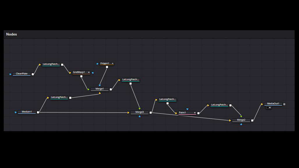
    The Node Layout:
    MediaIn1
    (Raw Video Source)
    LatLongPatcher1
    (Extract Mode)
    Your Cleanup Stream
    (Paint or Clean Plate)
    1. Import Media: Bring your original equirectangular footage (MediaIn1) into the Fusion grid.
    2. Add the Patcher: Press Shift + Spacebar, type LatLongPatcher, and add the node to your grid. Connect the output of MediaIn1 into it.
    3. Set to Extract: Select the LatLongPatcher node, navigate to the Inspector, and change the Method dropdown menu to Extract.
    4. Isolate the Object: Use the Pan (left/right) and Tilt (up/down) sliders to rotate the camera view until the object you want to remove (such as the tripod legs) is dead-center in your viewer window.
    5. Adjust Scale: Tweak the FoV (Field of View) slider to zoom in or out until you have a comfortable 2D workspace with enough surrounding texture around your object.

    Phase 2: Choosing Your Object Removal Method

    Depending on the complexity of your shot and whether the camera is moving, choose one of the following two professional removal workflows:

    Method 1: The Paint Node (Best for Stationary Shots & Organic Textures)

    This method is ideal for locked-off tripod shots or environments with organic textures—like grass, asphalt, or gravel—where you can easily clone pixels from a neighboring area.

    The Node Layout:
    LatLongPatcher1
    (Extracted 2D Window)
    Paint Node (Pnt)
    (Clone Tool Fixes)
    To Injection Stage
    (Phase 3 Setup)
    • Insert Paint: Add a Paint node directly after your extraction pipeline.
    • Select the Clone Tool: Look at the toolbar directly above the viewer window and select the Clone tool icon (represented by a rubber stamp).
    • Set Lifetime: In the Inspector, open the Stroke Controls tab. Change the Duration dropdown from Single Frame to All Frames. This ensures your paint stroke stays active across your entire timeline.
    • Sample and Clean: Hold down Alt (Windows) or Option (Mac) and click on a clean patch of texture near your target object to sample it. Release the key, and paint directly over the tripod or operator to clone the clean texture over it.

    Method 2: Clean Plate & GridWarp (Best for Complex Patterns & Dynamic Camera Movement)

    When the background texture is geometric (like floor tiles, brickwork, or hardwood floors) or when the camera is physically moving through space, a simple paint stroke will fail. This method utilizes an external clean plate still image and a GridWarp node to fix complex alignments.

    The Node Layout:
    LatLongPatcher1
    (Live Video Stream)
    [Background Input] Merge1 Node
    (Combines Streams)
    MediaIn2 (Clean Still)
    LatLongPatcher2 (Same Camera Matrix)
    GridWarp Node (Fixes Parallax Drift)
    [Foreground Input]
    The Reality of Parallax: Why We Need Motion Compensation

    It is a common misconception that camera mounts stay perfectly static relative to the background. If your camera is moving through an environment—whether it is mounted on a mechanical slider, pushed on a dolly, or rolling on a vehicle—and the object you want to remove is anchored to the environment (or if the camera moves independently of the support base below it), the physical distance between the camera lens and that object changes over time.

    As the camera approaches or recedes from the target area, spatial parallax occurs. The perspective lines of the floorboards, tile grouting, or brick patterns stretch, expand, and warp dynamically because the lens’s physical point of view is shifting. If you stamp a flat, static clean plate snapshot over this moving environment, it will look like a floating “sticker” within seconds because the ground underneath is physically changing perspective. To hide this asset cleanly, we must actively warp the texture to match the moving world.

    Step 1: Prep and Align the Clean Plate
    • Bring in the Still: Import your edited, tripod-free clean plate still image (MediaIn2) into your node graph.
    • Match the Viewport: Pipe it into a second LatLongPatcher node (LatLongPatcher2).
    • Crucial Alignment: Copy the exact Pan, Tilt, and FoV values from your first patcher and paste them into this second patcher. This ensures both 2D windows match pixel-for-pixel.
    Step 2: Correcting Perspective Shift with GridWarp
    • Insert Warp & Merge: Add a GridWarp node (GW) directly after your clean plate’s extraction pipeline. Connect its output into the Green Foreground Input of a Merge node (Merge1). Pipe your live video line (LatLongPatcher1) into the Yellow Background Input of that same Merge node.
    • Define the Source Mesh: Move your playhead to Frame 0. In the GridWarp Inspector, ensure the mode is set to Source. Sub-divide your grid using the X Grid and Y Grid sliders until you have a flexible mesh covering your clean plate area. Align the grid vertices with prominent lines on the floor (like grout lines or floorboard seams).
    • Warp the Destination: Move downstream to a frame where the camera movement has caused your clean plate texture to drift out of alignment with the live video background.
    • Correct Perspective Shift: In the Inspector, change the GridWarp mode dropdown from Source to Destination. Gently nudge the individual mesh vertices in your viewer. Warping the destination grid stretches and bends the static clean plate texture, forcing its perspective lines to realign perfectly with the moving background video as the camera’s spatial relationship to the ground changes.

    Phase 3: Injecting the Patch Back into the 360 World

    Once your object is cleanly painted out or perfectly perspective-warped, you must re-wrap your flat 2D patch back into a proper 2:1 equirectangular sphere.

    The Node Layout:
    Step 1: The Fix Stream
    Merge1 (Your Object Fix)
    Step 2: The Re-Wrap
    LatLongPatcher3 (Inject Mode)
    ▼ (Feeds into Foreground Input)
    Step 3: The Target Merge (Merge2)
    Combines the Inject Patch with the Raw Video Line (MediaIn1) as the Background
    Step 4: Terminal Render Target
    MediaOut1 Node
    1. Add the Injector: Place a final LatLongPatcher node (LatLongPatcher3) at the end of your clean patch stream.
    2. Set to Inject: In the Inspector, change the Method dropdown to Inject.
    3. Match the Viewport Matrix: Copy the exact Pan, Tilt, and FoV coordinates used in your initial extraction phase and paste them into this injection node. The node will automatically take your flat 2D fix, distort it spherically, and place it back precisely where it belongs in the 360-degree environment.
    4. Merge with Original Footage: Add a final Merge node (Merge2). Connect your original, untouched raw video line (MediaIn1) into the Yellow Background Input of the Merge node. Connect the output of your Injection node into the Green Foreground Input.
    5. Isolate with a Mask: To prevent your patch from accidentally overwriting clean areas outside your fix, attach a Polygon Mask node to the Blue Mask Input of the final Merge node. Draw a tight window around just your object removal area.

    Your final output from Merge2 will now display a flawless 360 video with the tripod or target object completely eliminated across the entire timeline, mapped perfectly to the sphere, and ready for your MediaOut1 node.

    About the Author:
    Daniel John Brown is a VR photographer, videographer, and founder of Meidansha. Based in Japan, he specializes in high-resolution immersive media and technical post-production workflows.
    Business & Portfolio: Connect with my corporate team at Meidansha.

    To see more on 360 photography and videography please see the category top

    360度映像のオブジェクト消去法:DaVinci Resolve FusionでLatLongPatcherを使いこなす

    360度動画制作における最大の課題の1つは、撮影時の機材やスタッフの痕跡をいかに隠すかということです。三脚のベース、カメラマンの映り込み、あるいは不自然な影など、完全に没入感のあるシーンを作るには、これらを綺麗に消去(オブジェクトリムーバル)する必要があります。

    しかし、360度正距円筒図法(エクイレクタングラー)のファイルを、通常のフラットな動画キャンバスと同じように扱うことはできません。映像が2:1の球状に投影されているため、通常のペイントツールやトラッキングツールを使って直接描き込むと、極部(画面の最上部・最下部)や左右の端で深刻な歪み(引き伸ばしや破れ)が発生してしまいます。

    この問題を解決するために、DaVinci Resolve StudioのFusionページに用意されている「LatLongPatcher」ノードを使用します。このノードは、全天球映像の特定の領域を、歪みのないフラットな2Dパースペクティブ(透視投影)ウィンドウへ非破壊で「展開(アンラップ)」してくれます。これにより、2D上で完璧な消去作業を行ってから、再びそのパッチを360度の世界へと戻すことが可能になります。

    フェーズ 1:コアとなる展開セットアップ

    オブジェクトを消去する前に、まずは対象のエリアをフラットで作業しやすい2Dキャンバスとして抽出する必要があります。

    ノードの配置構造:
    MediaIn1
    (未加工のビデオソース)
    LatLongPatcher1
    (Extract モード)
    クリーンアップ処理
    (ペイントまたはクリーンプレート)
    1. 素材のインポート: 元のエクイレクタングラー映像(MediaIn1)をFusionのグリッド内に読み込みます。
    2. Patcherノードの追加: Shift + スペースキーを押し、LatLongPatcherと入力してノードをグリッドに追加します。MediaIn1の出力をこのノードに接続します。
    3. Extractに設定: LatLongPatcherノードを選択し、インスペクタを開いて「Method」ドロップダウンメニューを「Extract」(抽出)に変更します。
    4. オブジェクトの分離: 「Pan」(左右)と「Tilt」(上下)のスライダーを動かしてカメラの視野を回転させ、消去したいオブジェクト(三脚の脚など)がビューアウィンドウの真ん中に来るように調整します。
    5. スケールの調整: 「FoV」(視野角)スライダーを微調整し、オブジェクトの周囲のテクスチャが十分に収まる、作業しやすい適度な広さの2Dワークスペースを作ります。

    フェーズ 2:オブジェクト消去手法の選択

    カットの複雑さや、カメラが動いているかどうかに応じて、以下の2つのプロフェッショナルな消去ワークフローから最適な方を選択します。

    手法 1:ペイントノード(固定ショット&有機的なテクスチャに最適)

    この手法は、三脚を完全に固定して撮影したショットや、芝生、アスファルト、砂利などの有機的なテクスチャを持つ環境に最適です。周囲の綺麗なエリアからピクセルを簡単にクローン(複製)して上書きできます。

    ノードの配置構造:
    LatLongPatcher1
    (抽出された2Dウィンドウ)
    Paint ノード (Pnt)
    (クローンツールによる修正)
    インジェクション工程へ
    (フェーズ 3 の準備)
    • 有効期間の設定: インスペクタの「Stroke Controls」(ストローク制御)タブを開きます。「Duration」(期間)ドロップダウンを「Single Frame」(1フレーム)から「All Frames」(全フレーム)に変更します。これにより、描いた修正ストロークがタイムライン全体で持続するようになります。
    • サンプリングとクリーンアップ: Altキー(Windows)またはOptionキー(Mac)を押しながら、消去したい対象の近くにある綺麗なテクスチャ部分をクリックしてサンプルを採取します。キーを離し、三脚や人の上に直接ブラシで描き込んで、きれいなテクスチャを上書きしていきます。

    手法 2:クリーンプレート & GridWarp(複雑な模様 & 動的なカメラワークに最適)

    背景のテクスチャが幾何学的(床のタイル、レンガ、フローリングなど)である場合や、カメラが空間内を移動している場合は、単純なペイントによる塗りつぶしは通用しません。この手法では、外部で編集した三脚のない静止画(クリーンプレート)と「GridWarp」ノードを組み合わせ、複雑な位置合わせをクリアします。

    ノードの配置構造:
    LatLongPatcher1
    (実景映像ストリーム)
    [背景入力] Merge1 ノード
    (ストリームの合成)
    MediaIn2(クリーン静止画)
    LatLongPatcher2 (カメラマトリクスを一致)
    GridWarp ノード (視差によるズレの補正)
    [前景入力]
    視差(パララックス)の現実:なぜ動きの補正が必要なのか?

    「カメラの台座は背景に対して常に完全に固定されている」というのは、よくある誤解です。カメラが電動スライダー、ドリー、あるいは移動する車両に設置されて空間内を移動しており、かつ消去したいターゲットが地面や壁に固定されている場合(またはカメラが下の支柱ベースとは独立して位置を変える場合)、カメラレンズと消去対象の物理的な距離は時間の経過とともに絶えず変化します。

    カメラが対象エリアに接近または後退するにつれて、空間的な「視差(パララックス)」が生じます。レンズの物理的な視点(Point of View)がシフトするため、床板のライン、タイルの目地、レンガの模様といったパース線が、動的に引き伸ばされたり、広がったり、歪んだりします。もし、この動く環境の上にフラットで静止したクリーンプレートをただ重ねただけでは、下の地面のパースが変化していくため、ものの数秒でパッチが浮いた「ステッカー」のように見えてしまいます。この機材跡をきれいに隠し通すには、移動する世界に合わせてテクスチャを能動的に歪ませる(ワープさせる)必要があります。

    ステップ 1:クリーンプレートの準備と配置

    • 静止画の読み込み: 外部で三脚を消去・加工済みのクリーンプレート静止画(MediaIn2)をノードグラフに読み込みます。
    • 画角の完全一致: これを2つ目のLatLongPatcherノード(LatLongPatcher2)に接続します。
    • 極めて重要な位置合わせ: 1つ目のPatcher(映像用)の「Pan」「Tilt」「FoV」の数値を完全にコピーし、この2つ目のPatcherにペーストします。これにより、双方の2Dウィンドウがピクセル単位で完全に一致します。

    ステップ 2:GridWarpによるパースのズレの補正

    • WarpとMergeの挿入: クリーンプレートを展開した直後に「GridWarp」ノード(GW)を追加します。その出力をMergeノード(Merge1)の「緑色の前景入力」に接続します。そして、動く実景映像のライン(LatLongPatcher1)を、同じMerge1の「黄色の背景入力」に接続します。
    • ソースメッシュの定義: タイムラインの「フレーム 0」に移動します。GridWarpのインスペクタで、モードが「Source」に設定されていることを確認します。「X Grid」「Y Grid」のスライダーを使ってグリッドを細かく分割し、クリーンプレートのパッチ範囲をカバーする柔軟なメッシュを作ります。グリッドの頂点を、床の目地やフローリングの継ぎ目など、目立つラインに合わせて配置します。
    • デスティネーションのワープ: カメラの移動によって、クリーンプレートのテクスチャが周囲の映像のラインからズレてきてしまっている、少し進んだ先のフレームへ移動します。
    • パースシフトの修正: インスペクタで、GridWarpのモードドロップダウンを「Source」から「Destination」(ディスティネーション)に変更します。ビューア上で、メッシュの各頂点をつまんで静かに動かします。目的地(Destination)のグリッドを歪ませることで、静止したクリーンプレートのテクスチャが伸縮・変形し、カメラと地面との位置関係の変化に伴って動く背景映像のパース線へと完璧に再整列させることができます。

    フェーズ 3:パッチを360度の世界へインジェクション(戻し)する

    オブジェクトがきれいにペイント消去されたか、あるいは完璧にパース補正されてマージされたら、そのフラットな2Dパッチを再び正しい2:1のエクイレクタングラー全天球へと戻す必要があります。

    ノードの配置構造:
    ステップ 1:修正済みのストリーム
    Merge1(オブジェクト修正箇所)
    ステップ 2:全天球への再カプセル化
    LatLongPatcher3(Inject モード)
    ▼ (前景入力へ接続)
    ステップ 3:合成用の最終マージ(Merge2)
    インジェクションしたパッチと、背景となる元の生の映像ライン(MediaIn1)を合成
    ステップ 4:最終レンダリング出力
    MediaOut1 ノード
    1. 戻し用Patcherの追加: クリーンパッチが完成したストリームの最後に、3つ目の「LatLongPatcher」ノード(LatLongPatcher3)を配置します。
    2. Injectに設定: LatLongPatcher3のインスペクタを開き、「Method」ドロップダウンを「Inject」(注入)に変更します。
    3. Viewportマトリクスの完全一致: 最初のフェーズ1(抽出時)で使用した「Pan」「Tilt」「FoV」の座標を完全にコピーし、このインジェクションノードにペーストします。これにより、ノードがフラットな2Dパッチを自動的に球状に歪ませ、360度の空間内の本来あるべき正確な位置へと配置してくれます。
    4. オリジナル映像との合成: 最後の「Merge」ノード(Merge2)を追加します。何も手を加えていない元の生映像ライン(MediaIn1)をMerge2の「黄色の背景入力」に接続します。そして、インジェクションノード(LatLongPatcher3)の出力を「緑色の前景入力」に接続します。
    5. マスクによる限定化: 修正パッチが、関係のない綺麗な領域まで誤って上書きしてしまわないように、「Polygon」マスクノードを最後のMerge2の「青色のマスク入力」に接続します。そして、オブジェクトを消去したエリアの周囲だけをタイトに囲むマスクを描きます。

    以上の工程により、Merge2からの最終出力は、三脚や機材がタイムライン全体にわたって完璧に消去され、全天球に完全にマッピングされた、非の打ち所がない360度動画となります。あとはこれを「MediaOut1」ノードへ送ればレンダリングの準備は完了です。

    著者について:
    ダニエル・ジョン・ブラウン(Daniel John Brown)は、VRフォトグラファー、ビデオグラファーであり、明段舎株式会社の代表。日本を拠点に、高解像度のイマーシブメディア(没入型メディア)の制作や、高度なポストプロダクションワークフローを専門としている。
    ビジネス&ポートフォリオ: コーポレートチームへのご連絡・ご依頼は Meidansha をご覧ください。

    360度動画や静止画編集について関心あればこのカテゴリーをご確認ください。

  • 8K VR Proxy Workflow in Davinici Resolve Studio 20

    8K VR Proxy Workflow in Davinici Resolve Studio 20

    8K VR Proxy Workflow in DaVinci Resolve Studio 21

    8K VR Proxy Workflow in Davinci Resolve Studio 21

    This is a how-to article for 8K VR Proxy workflow in Davinici Resolve Studio 21. Editing high-bitrate, stitched 8K equirectangular files is notoriously brutal on computer hardware. Even on high-end Windows workstations, scrubbing natively through raw 8K 360-degree footage can easily turn your timeline into a choppy slideshow.

    To maintain a smooth creative flow, a proxy workflow is a necessity. However, if you try to use DaVinci Resolve Studio’s built-in “Generate Proxy Media” tool or the standalone Blackmagic Proxy Generator, you will hit a frustrating bottleneck: they force a standard 16:9 aspect ratio (like 1920×1080), squashing your perfect 2:1 spherical footage and breaking your stitching preview. Furthermore, batch-relinking these standard proxies fails completely with this format.

    To solve this, we must use a manual transcoding workflow that bypasses the automated proxy generator entirely, keeping your 2:1 aspect ratio intact and restoring silky-smooth playback. Here is the exact step-by-step blueprint.

    Phase 1: Review & Preparation (Insta360 Studio)

    The sole objective of this phase is to trim your raw data and prep it into a clean, “flat” master file. Do not waste time attempting to set a Point of Interest (POI) or altering your angles here; Insta360 Studio completely ignores timeline orientation and framing adjustments when exporting a clip as a true 360 video.

    1. Technical Setup

    • Lens Guard: In the Right Sidebar, click the Media Tab (first icon). Scroll down to Accessories and manually select Standard or Premium depending on your physical setup. Do not leave this on “Auto.”
    • Stitching: In the same Media Tab, scroll to Stitching Settings and select Optical Flow Stitching for the cleanest seams.
    • Stabilization: Leave this on its default FlowState Stabilization setting.

    2. The Timeline Cut

    • Trimming: Because we aren’t adjusting angles, your only task on the timeline is trimming. Move the playhead on the Bottom Timeline and use the Yellow Brackets to isolate and mark the exact section of the clip you want to export.

    3. High-Fidelity Export Settings

    Click the Yellow Export Icon (Bottom Right) and apply these settings to ensure your master file remains uncompressed and grade-ready:

    • Export Type: 360 Video
    • Resolution: 7680 x 3840 (8K)
    • Codec: ProRes 422 HQ
    • Image Processing: Uncheck both Color Plus and Remove Grain.
    • Keep it Flat: Do not add any sharpening and do not attempt any color grading inside Insta360 Studio. Keep the footage completely clean for the edit suite.

    Phase 2: The Windows-Optimized Proxy Workflow

    Now for the workaround. Because Resolve’s standard proxy tools ruin the 2:1 aspect ratio, we will use the Media Management tool to transcode custom, lightweight 2:1 proxies that Windows can handle natively.

    1. Transcode to MP4 (The Custom Method)

    Open DaVinci Resolve Studio and navigate to the Media Page (the first icon at the bottom).

    1. Select Your Footage: Highlight your newly exported 8K ProRes clips in the Media Pool.
    2. Open Media Management: Go to the top menu and select File > Media Management… then click on the Transcode tab at the top of the pop-up window.
    3. Configure the Custom 2:1 Settings: Set the parameters precisely to avoid the squash bug:
      Select: “All media” or “Selected timeline clips.”
      Format: MP4
      Video Codec: H.265
      Resolution: Select Custom and manually enter 1920 x 960 (for ultra-light 2K proxies) or 3840 x 1920 (for 4K proxies).
    4. Execute Transcode: Click Browse, select a dedicated Proxy folder on your fast external SSD, and click Start. Windows handles these custom H.265 MP4s seamlessly.

    2. Linking the Manual Proxies (Overcoming the Extension Deficit)

    Because you didn’t use Resolve’s standard “Generate Proxy” button, the automatic linker will often fail when you right-click the camera original and attempt a standard folder link. This happens because your master files are .mov (ProRes) and your proxies are .mp4 (H.265).

    To pair them properly without crashing your workflow, you have two options:

    • The Single File Method: If you only have a few clips, highlight your original 8K master clips in the Media Pool, right-click, and select Relink Proxy Media. Select the target file individually one by one.
    • The Batch Workaround (Loose File Match): If you are linking dozens of files, you need to use an advanced reconform search that tells DaVinci to find matching names while ignoring the file extension. Import your newly transcoded proxies into a separate bin. Select your main timeline, right-click and choose Timelines > Reconform from Bins. Under the match criteria, ensure File Name is checked and set it specifically to Loose file name match. Point it at your proxy bin, and Resolve will instantly jump the gap between the .mov and .mp4 containers.

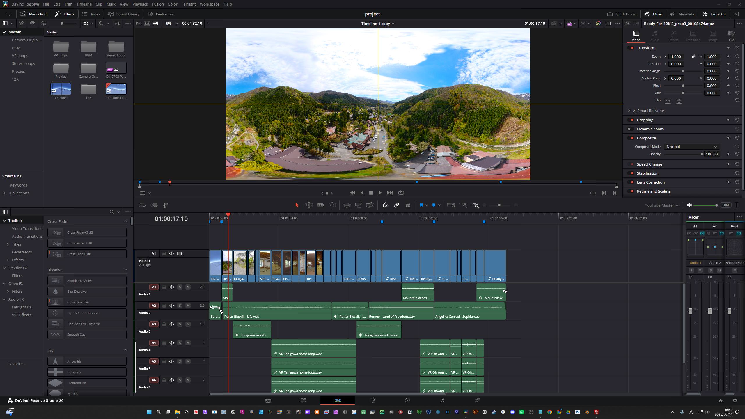
    Once linked, a small “pxy” icon will appear on your clips, confirming your aspect ratio is now a perfect, unsquashed 2:1 sphere.

    Mastering the Timeline Setup & Final Export

    When you are finished cutting your edit with proxies and are ready to color grade, match your master workflow, and export, you must configure your timeline correctly to ensure the final 8K delivery actually renders out without issues.

    1. Match Timeline to HQ Master Resolution

    Before hitting render, you must change your timeline settings to match the exact resolution of your high-quality master clips.

    • Right-click your active timeline in the Media Pool and select Timelines > Timeline Settings.
    • Uncheck “Use Project Settings.”
    • Set the resolution to your target master size: 7680 x 3840.

    2. Eliminate Black Bars & Check Project Settings

    Working with a true 2:1 equirectangular sphere means any structural mismatch will introduce accidental letterboxing or pillarboxing.

    • The Visual Check: Scan your timeline viewer to ensure there are no unintended black bars on the top, bottom, or sides of your image.
    • Image Scaling: In your master Project Settings, verify that your output scaling and aspect format match your target resolution perfectly. If your media aspect ratios are mismatching, ensure your input scaling is set to fill the frame cleanly without destroying the 360 geometry.

    3. Critical Render Deliver Page Check

    When you move over to the Deliver page to export your master file, there are two distinct settings you must check to ensure you don’t accidentally bake your low-resolution proxies into your final film:

    1. Go to the top menu: Playback > Proxy Handling and ensure it is set to Prefer Originals or Disable Proxies. Verify the change by looking for the small “HQ” badge replacing the “pxy” badge on your timeline clips.
    2. On the Deliver page sidebar, expand the Advanced Settings drop-down under the Video Export tab. Ensure that “Use proxy media” is unchecked. If left checked, Resolve will export your final master using the 2K transcoded files instead of your 8K ProRes masters.

    Why This Fixes “Jerky Playback”

    By using the Media Management tool instead of standard proxy generation, you optimize your system on three fronts:

    • The Container: Forcing an MP4 wrapper ensures smooth, native OS playback on Windows.
    • The Resolution: Dropping the resolution to 1920×960 asks your GPU to process a mere 1/16th of the data compared to the native 8K master.
    • Fusion Efficiency: Because the core video stream is now light, your system has massive overhead remaining to compute complex nodes, effects, and VR tracking—meaning your Fusion edits will be a lot smoother throughout the entire post-production pipeline.

    About the Author:
    Daniel John Brown is a VR photographer, videographer, and founder of Meidansha. Based in Japan, he specializes in high-resolution immersive media and technical post-production workflows.
    Business & Portfolio: Connect with my corporate team at Meidansha.

    To see more on 360 photography and videography please see the category top

    8K360度動画:DaVinci Resolve Studio 20でのプロキシー・ワークフロー

    高ビットレートでスティッチされた8Kのエクイレクタングラー(正距円筒図法)ファイルを編集するのは、PCハードウェアにとって非常に過酷な作業です。ハイスペックなWindowsワークステーションであっても、撮影したままの生の8K 360度映像をそのままスクラブしようとすると、タイムラインがカクつき、スライドショーのようになってしまいます。

    快適にクリエイティブな編集作業を進めるためには、プロキシワークフローが不可欠です。しかし、DaVinci Resolve Studio 21の内蔵「プロキシメディアの生成」ツールや、単体のBlackmagic Proxy Generatorを使おうとすると、不満の残る大きな壁にぶつかることになります。これらのツールは強制的に標準の16:9アスペクト比(1920×1080など)でプロキシを生成するため、せっかくの2:1の全天球映像が左右に潰れてしまい、スティッチのプレビューが崩れてしまうのです。 さらに、このフォーマットでは、生成された標準プロキシの一括再リンク(リリンク)も完全に失敗してしまいます。

    この問題を解決するには、自動のプロキシジェネレーターを完全にバイパスし、2:1のアスペクト比を維持したままスムーズな再生を実現する「手動トランスコード・ワークフロー」を使用する必要があります。その具体的なステップを以下に解説します。

    フェーズ 1:確認とエクスポート準備(Insta360 Studio)

    このフェーズの唯一の目的は、未加工のデータをトリミングし、クリーンで「フラット」なマスターファイルに仕上げることです。Insta360 Studioでは、クリップを真の360度動画としてエクスポートする場合、タイムライン上の方向(オリエンテーション)や画角(POI)の設定は完全に無視されます。 そのため、ここでアングル調整などに時間を費やす必要はありません。

    1. テクニカルセットアップ

    • レンズガード: 右サイドバーの「メディア」タブ(最初のアイコン)をクリックします。「アクセサリー」までスクロールし、実際の撮影環境に合わせて「標準」または「プレミアム」を手動で選択します。絶対に「自動」のままにしないでください。
    • スティッチング: 同じ「メディア」タブ内で「スティッチング設定」までスクロールし、継ぎ目が最も自然になる「オプティカルフロースティッチ(Optical Flow Stitching)」を選択します。
    • 手ブレ補正: デフォルトの「FlowState手ブレ補正」のままにしておきます。

    2. タイムラインのカット(トリミング)

    • トリミング: アングルの調整は行わないため、タイムライン上での作業はトリミングのみとなります。下のタイムラインで再生ヘッドを動かし、黄色のブラケット(角括弧)を使って、エクスポートしたいクリップの範囲を指定します。

    3. 高画質エクスポート設定

    右下の黄色の「エクスポート」アイコンをクリックし、マスターファイルの画質を落とさずに編集へ回せるよう、以下の設定を適用します。

    • エクスポートタイプ: 360度動画
    • 解像度: 7680 x 3840 (8K)
    • コーデック: ProRes 422 HQ
    • 画像処理: Color Plusノイズ除去の両方のチェックを外します
    • フラットな状態を維持: Insta360 Studio内ではシャープネスを追加せず、カラーグレーディングも行わないでください。編集ソフト側で本格的な作業ができるよう、映像は完全にクリーンな状態で出力します。

    フェーズ 2:Windowsに最適化したプロキシワークフロー

    ここからが回避策の本番です。Resolveの標準プロキシツールでは2:1のアスペクト比が崩れてしまうため、代わりに「メディア管理」ツールを使い、Windowsがネイティブで快適に処理できる軽量なカスタム2:1プロキシをトランスコードします。

    1. MP4へのトランスコード(カスタム方法)

    DaVinci Resolve Studioを開き、画面最下部にある「メディア」ページ(一番左のアイコン)に移動します。

    1. 素材の選択: メディアプール内で、先ほどエクスポートした8K ProResクリップを選択(ハイライト)します。
    2. メディア管理を開く: 上部メニューから「ファイル」>「メディア管理…」を選択し、表示されたウィンドウの上部にある「トランスコード」タブをクリックします。
    3. カスタム2:1設定の構成: 画面が潰れるバグを回避するため、以下のパラメータを正確に設定します。
      選択: 「すべてのメディア」または「選択したタイムラインのクリップ」
      フォーマット: MP4
      ビデオコーデック: H.265
      解像度: 「カスタム」を選択し、手動で「1920 x 960」(超軽量な2Kプロキシの場合)または「3840 x 1920」(4Kプロキシの場合)を入力します。
    4. トランスコードの実行: 「ブラウズ」をクリックし、高速な外付けSSD内に作成したプロキシ専用フォルダを指定して、「開始」をクリックします。WindowsはこれらのカスタムH.265 MP4ファイルをネイティブでスムーズに処理できます。

    2. 手動プロキシのリンク(拡張子の違いを克服する)

    Resolveの自動「プロキシ生成」ボタンを使用しなかったため、元のカメラ素材を右クリックして通常のフォルダリンクを試みても、自動リンカーが失敗することがよくあります。これは、マスターファイルが.mov(ProRes)であるのに対し、プロキシファイルが.mp4(H.265)と、拡張子が異なっていることが原因です。

    ワークフローを停滞させずにこれらを正しくペアリングするには、2つの方法があります。

    • 個別ファイル個別リンク法: クリップ数が少ない場合は、メディアプール内の元の8Kマスタークリップを選択し、右クリックして「プロキシメディアを再リンク」を選択します。対象のプロキシファイルを1つずつ手動で指定してリンクしていきます。
    • バッチ処理での回避策(緩やかなファイル名一致): 大量のファイルをリンクする必要がある場合は、拡張子を無視して一致するファイル名を探すようDaVinciに指示する、高度な「再コンフォーム」機能を使用します。まず、新しくトランスコードしたプロキシを別のビン(フォルダ)にインポートします。次に、メインのタイムラインを右クリックし、「タイムライン」>「ビンから再コンフォーム」を選択します。一致条件の項目で「ファイル名」にチェックを入れ、設定を「緩やかなファイル名一致(Loose file name match)」にします。ターゲットとしてプロキシの入ったビンを指定すると、Resolveは.mov.mp4のコンテナの違いを瞬時に飛び越え、すべてのファイルを一括でリンクしてくれます。

    正しくリンクされると、クリップに小さな「pxy」アイコンが表示され、アスペクト比が潰れていない、完璧な2:1の全天球映像になっていることが確認できます。

    タイムライン設定と最終エクスポートの極意

    プロキシを使ったカット編集が終わり、カラーグレーディングやマスターワークフローへの移行、および最終エクスポートの準備が整ったら、8Kの最終出力がトラブルなくレンダリングされるよう、タイムラインを正しく設定する必要があります。

    1. タイムラインを高画質マスターの解像度に合わせる

    レンダリングを開始する前に、タイムラインの設定を高画質のマスタークリップと全く同じ解像度に変更する必要があります。

    • メディアプール内のアクティブなタイムラインを右クリックし、「タイムライン」>「タイムライン設定」を選択します。
    • 「プロジェクト設定を使用」のチェックを外します。
    • 解像度をターゲットであるマスターサイズ:7680 x 3840に設定します。

    2. 黒帯の排除とプロジェクト設定の確認

    真の2:1エクイレクタングラー映像を扱う際、設定に少しでも不一致があると、意図しないレターボックス(上下の黒帯)やピラーボックス(左右の黒帯)が発生してしまいます。

    • 目視での確認: タイムラインビューアを細かくチェックし、映像の上下左右に意図しない黒帯が入っていないか確認します。
    • 画像のスケーリング: マスターの「プロジェクト設定」を開き、出力スケーリングとアスペクト比のフォーマットが、ターゲットの解像度と完全に一致しているか確認します。もし素材のアスペクト比にズレがある場合は、360度のジオメトリ(球体の形状)を崩さないように注意しながら、フレームが綺麗に埋まるよう入力スケーリングを設定してください。

    3. レンダリング時のデリバーページでの重要な確認項目

    マスターファイルをエクスポートするために「デリバー」ページに移動した際、低解像度のプロキシメディアが最終映像に誤って焼き付けられてしまうのを防ぐため、2つの設定を必ず確認してください。

    1. 上部メニューの「再生」>「プロキシの処理」に移動し、「オリジナルを優先」または「プロキシを無効化」に設定されていることを確認します。タイムライン上のクリップの「pxy」バッジが、高画質を示す「HQ」バッジに切り替わっていることで確認できます。
    2. デリバーページのサイドバーにある「ビデオ」エクスポートタブを開き、「詳細設定」ドロップダウンを展開します。「プロキシメディアを使用」のチェックが外れていることを必ず確認してください。 ここにチェックが入ったままだと、Resolveは8K ProResマスターではなく、トランスコードした2Kのプロキシファイルを使って最終出力をレンダリングしてしまいます。

    なぜこの方法で「再生のカクつき」が直るのか?

    標準のプロキシ生成ではなく、「メディア管理」ツールを使用することで、システムへの負荷を3つの側面から最適化できます。

    • コンテナの最適化: MP4ラッパーを強制することで、Windows環境においてOSネイティブでのスムーズな再生が可能になります。
    • 解像度の削減: 解像度を1920×960に落とすことで、GPUが処理すべきデータ量はネイティブの8Kマスターと比較してわずか16分の1になります。
    • Fusionの効率化: コアとなるビデオストリームが非常に軽量になるため、PCシステム側には複雑なノードやエフェクト、VRトラッキングの計算を行うための莫大な余力が残ります。結果として、ポストプロダクションの全工程を通してFusionでの編集作業が格段にスムーズになります。

    著者について:
    ブラウン・ダニエルジョン(Daniel John Brown)は、VRフォトグラファー、ビデオグラファーであり、明段舎株式会社の代表。日本を拠点に、高解像度のイマーシブメディア(没入型メディア)の制作や、高度なポストプロダクションワークフローを専門としている。
    ビジネス&ポートフォリオ: コーポレートチームへのご連絡・ご依頼は 明段舎 のウェブサイトをご覧ください。

    360度動画や静止画編集について関心あればこのカテゴリーをご確認ください。

  • A New Toy!

    A New Toy!

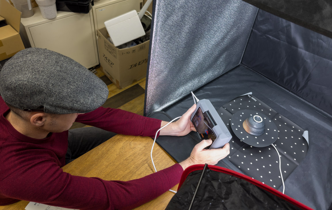
    今年1月に初めてのクラウドファンディングの応募で、CampfireでRevopoint社のMiracoという「物」の詳細をレーザースキャンをするLiDAR機器を買いました。

    なんと、日本国内の7人目の応募者となりました!

    明段舎は建物や屋外の景色を専用のレーザースキャナーやドローン・ミラレスカメラなどで撮影する会社なのです。ところが、同じレーザースキャナーでも「『物』の3Dはできませんか?」3回頼まれ、3回断らざるを得なかった昨年でMiracoを欲しくなりました!

    はじめて使っての感想ですが、非常に使いやすいものの、詳細な物の画像の撮影後の処理は建物の広く浅く撮影する画像と比べて手間がかかります。建物とは撮影時と事後処理の難易度は真逆です。

    でも、三次元的に撮影したものがパソコンの画面に表れてくる時の楽しみと感動はすごいです!

    初めての対象が、作るのに1時間以上手作業がかかる「和菓子」です。近日中画像の公開とブログをアップデートします!